Anybody that visits this site on a regular basis will notice that I have not been posting much lately. The reason for this, aside from my laziness is that I have been working on another project with my partner-in-crime – Mitul Patel. This time we have been doing some more work on his parents mini-supermarket. This time there I have taken a series of photos to show the saga.

This photo was taken in July 2010, almost two years ago to the day. At this point I had only known Mitul for a couple of months and he asked me to come and take a look at his parents CCTV system because the power supply had failed and he wasn’t sure what the installer guy* had done.
What the guy had done was a cowboy bodge job. The power supply on the left is a very cheap ATX type PSU which he had bridged the power-on connection such that it was running on its own. The mess of cables on the floor next to it is the 16 analogue feeds for the cameras, connected to video baluns and in turn connected to a couple of Cat5e Ethernet cables which he had used to wire the cameras.

Looking up in the suspended ceiling, the situation was even worse. Because of how he had wired these cameras, it was a bodge of bad connectors and a rats nest of Ethernet cable. Mitul and I suggested that the simplest solution to get everything working properly would be to replace the cabling and terminate it into a 19 inch rack. This was to become our first “Summer Project.”
*Oh, for the record I have been told by Mitul that the installer was Terry Williams and that the video capture card he used was counterfeit. To add insult to injury, for this crap installation, he charged a very non-crap price.

To tidy the installation up, we installed a 19 inch rack on the countertop, which was then screwed down for security, and a hardwired power supply installed into the case.

The CCTV server then sat on the shelf inside the rack. The side panel has been removed for viewing.
Behind the server you can see the RG59U coaxial cables which have replace the crap Ethernet ones. There is a single feed for each camera and power is now drawn from the 12V rail of the main power supply, however when the computer system is upgraded, a separate CCTV power supply will be installed. There are also KVM feeds from the front console to the server.

Small things such as a cover on the top cable entry slot left the installation tidy after five days of work. The installation then worked perfectly up until the weekend before last when the next project started.
As I have mentioned previously, Mitul is studying for his Cisco CCNA qualification, so wanted to do a Cisco installation as a practical exercise. This presented a number of problems though. First, the rack was not big enough to accommodate the necessary router and switch, so a bigger rack would be needed. It was also decided that this one would be placed at high level to stop it being tampered with and to free up desk space. Cat6 FTP shielded cable would be installed throughout, terminated into faceplates strategically placed for Cisco 7960G IP phones and a Cisco Aironet 1242.
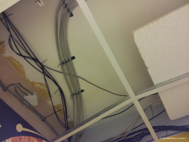
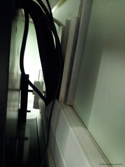
After removal of the old rack, and the transfer of the CCTV server to a new Chenbro RM41300 4U rackmount chassis the cable was installed in the ceiling void. The cable was installed carefully to prevent the cables becoming damaged and to keep everything neat. The thin white cable is the telephone line for analogue voice. The other black cables are data and power cables for the CCTV system.

The old conduit around the beam was removed to make room for the additional cables prior to being boxed in later.

The cables were dropped down in 20mm plastic conduit into a backbox with a network faceplate.
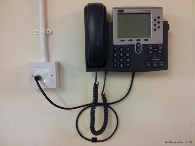
From the faceplate a Cat6 FTP cable connects to the phone which is also wall mounted in the stock room. For tidiness the cable is tied back to the wall.

In order to keep the appearance of the shop tidy and to reduce the chance of the device getting damaged or stolen, the Aironet is to be positioned in the ceiling void.

The Aironet is then installed on its faceplate and connected to a network outlet module.

At the front of the shop, additional ports are provided in case Mituls parents decide to upgrade to a network connected EPOS system. To prevent unwanted devices being connected, port security will be enabled on the switch such that the port will be shutdown should an unapproved device be connected.

Looking at the cost of suitable racks, and the requirements of the installation, we decided to build a rack instead. This is made of 2×2 timbers which have been painted and then fitted together. The front edge holds a pair of 12U 19 inch rack strips. The two arms off to the left are to hide the incoming cabling when the rack is installed.

The equipment was then test fitted. The server sits at the bottom of the rack above a 1U blanking/spacing plate. Above the server is a 3U blanking plate to give room for hiding excess cabling. Above this is the Cisco 2811 router. The switch and the patch panel are not currently installed. We decided that in homage to 2001: A Space Odyssey the server should be named HAL owing to the light at the centre of it. Yes, we know it’s blue not red. but if they made the film today then they’d probably use a blue light!
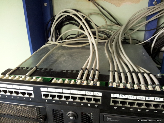
Once the rack was installed, the patch panel was connected. In total there are 14 patches consisting of an analogue voice connection to the telephone network, an internet feed, 4 patches to the office (labelled O1-O4), 2 patches to the stock room (S1/S2), two patches to the mid-span (M1/M2) and 4 patches to the shop front (F1-F4.)
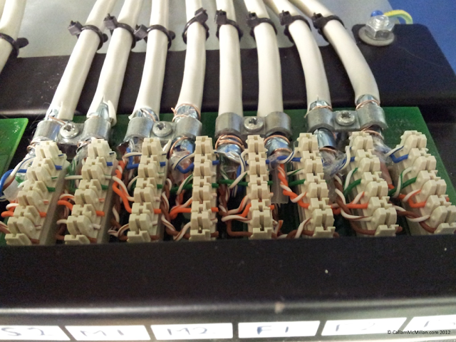
Each cable is first tied to the panel arm to stop is pulling loose or becoming tangled. Next the drain wire is wrapped around the foil shielding and terminated under the earth clamp. Then the 8 cores are terminated into their respective punch-down blocked. Looking at the rear-right of the panel you can see the screw holding the earth cable in place which connects back to the building earth.

The front of the patch panel is then fully labelled for ease of installation and maintenance. Enough slack cable is provided for the patch panel to be moved around. Before the next phase of the installation, the panel is moved to the very top of the rack.

The router and switch are now installed along with the patch cables.

The position of the rack in the office. Cables for the keyboard, mouse and monitor all run in the plastic conduit in the corner.

A close-up of the equipment. The switch is a Cisco 3560 24 port PoE switch while the router is a Cisco 2811.
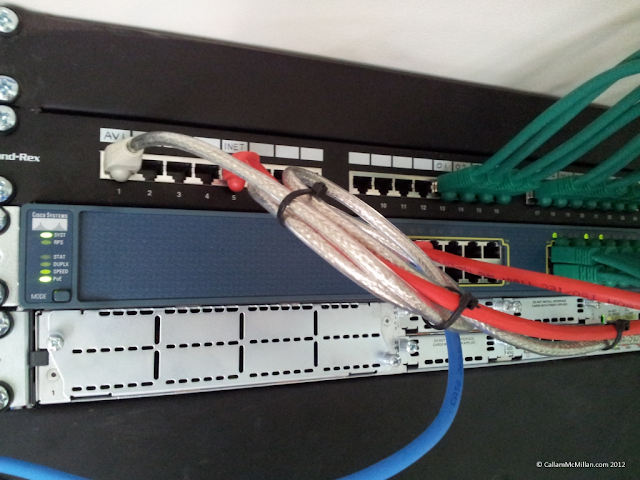
The switch is powered up and is showing the phones and aironets are drawing their power from the switch.

The router interfaces. Internet comes from the modem via FastEthernet0/0 and the router-switch connection is via FastEthernet0/1. The analogue voice line terminates into port0 of a VIC2-4FXO card.

The rest of the phones are connected up in their final locations.

The sign of a professional/well-considered job. We provided a USB cable at low level for connecting USB devices, which we tied back to the wall to stop it getting lost or tangled.

A clutter free workstation. At a later date a desktop may be added and there is now space to do so. A KVM can easily be installed so there is no need for additional keyboards and mice.

The cables running around the beam are now boxed back into place. Aluminium edging hides the rough edges of the wood and ceiling tiles in order the make the finished result look more professional.

The new phone at the front of the shop awaiting setup. Fortunately this bit is down to Mitul as my knowledge of Cisco doesn’t extend to full voice setups.

Phew, after two weekends work, the job is finally done and everything tidied. The shelving has been cut down in width to make more room and everything has been tided. The last job that may be necessary is to repaint the rear wall of the office where the paint has been removed by the old conduit.
Sadly, this isn’t the last I’m likely to see of this shop, the next bit of work likely to need doing is to rewire the telephone and light switch board at the front of the shop which is so congested and difficult to access that the BT engineer may not be able to get to it in order to install the new internet connections. If I end up working on that, be assured, photos will follow!

Nice setup! How long did it take to do?
This is usually done with BGP muitnhomlig or PBR. I do PBR at my company. One link we use for voice and the other for general data. It is quite simple to do PBR, simple route map while setting the next hop default for the gateway and a match statement for the networks you want to route using an ACL. Another way I could think of doing it would be have two gateways, one for each ISP and just use GLBP to actually load balance the final gateway, since it uses a virtual IP and MAC, you can balance based on many factors (VRRP or HSRP could also accomplish something similar, but you would have to manually balance by source, much like PBR).Forgot to mention you could use NAT load balancing or PfR (used to be known as OER) to do this as well. Then there is always multiple default routes, you just have to have CEF enabled and pick your CEF load balance scheme.More info would help, but there is a ton of ways.CCNP, CCDP, CCIE written, Network Engineer for a Cisco partner